
The goal for this week is to render a single triangle using WebGPU and understand the concept of the render pipeline a bit more.
The Rendering Pipeline
WebGPU’s API is based more on graphics APIs such as Vulkan and Metal than on OpenGL. That’s why we don’t call it “WebGL 3.0”. That said, we have more power to configure it compared to WebGL, and that’s why I want to talk about the rendering pipeline.
⚠️The scope of this discussion will be limited to a high level. If you want to dig deeper, I recommend you view this Computer Graphics playlist by Keenan Crane

The rendering pipeline where the green boxes are designated as programmable (not fixed).
Input
The input to the pipeline is the information we provide to the GPU from the CPU, such as buffers or textures, and whatever else may be required to render a scene.
The data we probably want to provide is information about:
- 3D models
- The coordinates of the vertices
- Local transformations
- Colors, materials
- Lights
- Camera
- Information about an interaction with the user
- …other things in the scene.
The Vertex Shader
Shaders are programmed by us, which is important because almost the entire rendering pipeline is fixed (or non-programmable).
A shader is defined by Wikipedia as the following:
In computer graphics, a shader is a type of computer program originally used for shading in 3D scenes (the production of appropriate levels of light, darkness, and color in a rendered image).
The vertex shader runs once for each vertex on the GPU. It takes vertices and their attributes as input. Regarding the position of a vertex, it processes and applies transformations in order to place them from 3D space into 2D screen space.
Here, one usually transforms the vertices with respect to the camera by applying a sequence of transformation matrices.
    void main()
    {
        gl_Position = gl_ModelViewProjectionMatrix * gl_Vertex;
    }
A basic vertex shader implementation in GLSL
Transformations
I would like to quickly explain the transformations that are often used to transform the position of a vertex before continuing. We will come back to this when we develop our scene in a later part.
It is important to remember that these transformations aim to change the position of the vertex from one coordinate space to another.
Model space
In computer graphics, a 3D model is created in a space specific to the model which is called model space.

World space
World space is the space in which the scene is defined. Position and orientation of 3D objects, camera, lights are included. We apply the model-world transformation to transform our models into world space.
View space
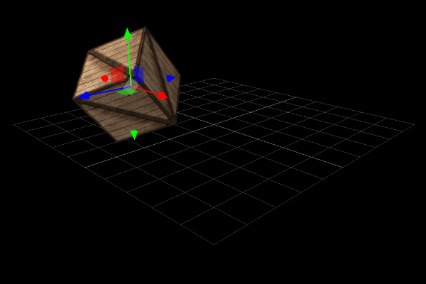
The camera is usually the world reference in a scene (i.e. the camera is the origin of it and looking down the positive z-axis). It is therefore necessary to move the world in relation to the position and orientation of the camera.
In other words, if you want to see the world upside down, you would just turn the whole world upside down and not turn the camera! To do this, we apply the view transformation. Without applying the projection transformation, we see the world from an orthographic camera.

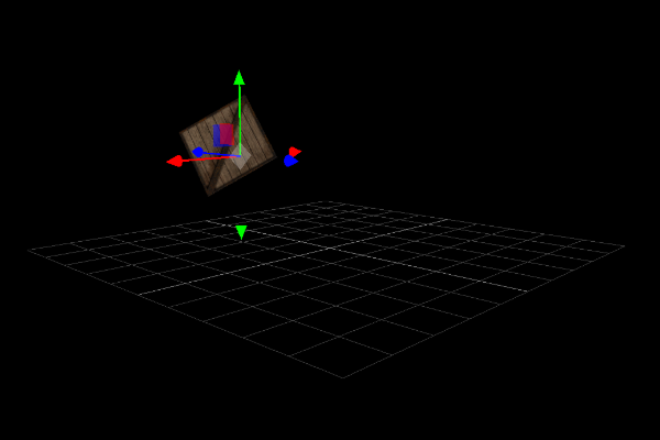
Finally, to see the world through a perspective camera, we apply the projection transformation to get the following result:
Assembly and Rasterization of primitives
After transforming our vertices from 3D space to 2D space (in view from our camera), the GPU must assemble, clip (in a process called clipping), and rasterize (pixelate) our primitives. This process is responsible for transforming our vertices, which are described in 3D, into pixels on the screen in 2D.
⚠️As I said, the goal is not to do a doctoral thesis. We will return to these topics in depth during our project.
The Fragment Shader
Finally, the fun of the rendering pipeline! We are in charge of programming this shader, which has only one job - to provide the color of one pixel (fragment). This program is executed on every fragment of every frame!
More precisely, the fragment shader takes as input the attributes of the vertices which have interpolated values and its role is to calculate the final color on the screen of the fragment (pixel) provided by the rasterization step.
After processing each pixel and resolving the visibility of each object, the image is rendered, and then appears on the screen.
WebGPU and our first triangle
⚠️ To view the code, you must use a browser with the WebGPU flag enabled. See this resource for more information.
⚠️ I assume basic knowledge on the subject of graphics APIs (like WebGL)
The code is in my codebase that accompanies this blog.
WebGPU is part of the new generation of rendering, created for the web. If you’re experienced in other graphics APIs, you’ll be more comfortable than not having any. Anyway, after a bit of time and practice, you’ll see that it’s not that hard to figure out how to create cool projects!
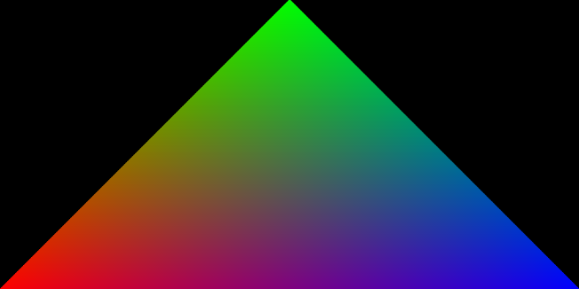
I propose that we create a triangle to introduce ourselves to the WebGPU API.
Adapter and Device
We first start by ensuring the availability of WebGPU in our browser:
// ~~ INITIALIZE ~~ Make sure we can initialize WebGPU
if (!navigator.gpu) {
    console.error("WebGPU cannot be initialized - navigator.gpu not found")
    return null;
}
const adapter = await navigator.gpu.requestAdapter();
if (!adapter) {
    console.error("WebGPU cannot be initialized - Adapter not found")
    return null;
}
const device = await adapter.requestDevice();
device.lost.then(() => {
    console.error("WebGPU cannot be initialized - Device has been lost")
    return null;
});

const canvas = document.getElementById("canvas-container")
const context = canvas.getContext('webgpu');
if (!context) {
    console.error("WebGPU cannot be initialized - Canvas does not support WebGPU")
    return null;
}
What is an adapter and a device?
-
Adapter - it’s like
VkPhysicalDevice(if you are experienced in Vulkan). WebGPU allows us to get a list of all the GPUs in our computer. You can also pass an argument to the function to select a GPU of a certain type. If you have multiple GPUs in your system, for example, like in a laptop with a low-power GPU for battery-powered use and a high-powered GPU for plugged-in use. -
Device - it’s like
VkDevice. This is the GPU driver on the hardware graphics card and our method of communicating with it. Theoretically, you can create several devices in order to communicate between several GPUs.
Swap Chain
After creating the Canvas context, we configure it like so:
    const devicePixelRatio = window.devicePixelRatio || 1;
    const presentationSize = [
        canvas.clientWidth * devicePixelRatio,
        canvas.clientHeight * devicePixelRatio,
    ];
    const presentationFormat = navigator.gpu.getPreferredCanvasFormat();

    context.configure({
        device,
        format: presentationFormat,
        alphaMode: "opaque"
    });
These lines of code may look weird and abstract… we are setting up the swap chain and the Canvas context at the same time. In fact, if you view a WebGPU tutorial from the past, you might see the deprecated method where you explicitly set up the swap chain.
What is a swap chain? The main role of the swap chain is to synchronize the presentation of our generated images with our screen refresh rate. It is a queue that contains images waiting to be displayed. We can configure how it works by passing parameters to the context.configure method.
Vertices
const vertices = new Float32Array([
    -1.0, -1.0, 0, 1, 1, 0, 0, 1,
    -0.0, 1.0, 0, 1, 0, 1, 0, 1,
    1.0, -1.0, 0, 1, 0, 0, 1, 1
]);

const vertexBuffer = device.createBuffer({
    size: vertices.byteLength,
    usage: GPUBufferUsage.VERTEX | GPUBufferUsage.COPY_DST,
    mappedAtCreation: true
});
new Float32Array(vertexBuffer.getMappedRange()).set(vertices);
vertexBuffer.unmap();

const vertexBuffersDescriptors = [{
    attributes: [
        {
            shaderLocation: 0,
            offset: 0,
            format: "float32x4"
        },
        {
            shaderLocation: 1,
            offset: 16,
            format: "float32x4"
        }
    ],
    arrayStride: 32,
    stepMode: "vertex"
}];
What’s special here is that we have to pack our array of vertices into a single giant array buffer. Each vertex consists of six floats in this case (three to represent position, and three to represent color). If we want to include other attributes, we must add more floats to each vertex.
After defining our vertices, we create the vertexBuffer which is the buffer that will live in the GPU. We are responsible for filling it at this point. The act of “mapping” a buffer is important to its operation. A mapped buffer means that the CPU can write to it and the GPU cannot. Conversely, if the buffer is unmapped, the GPU will be able to read it, and the CPU will be prohibited.
This is why we designate mappedAtCreation as true during the creation stage. We can then invoke .set to copy our vertices into the buffer. Finally, we remove the CPU’s write access, and grant GPU read access, by calling vertexBuffer.unmap().
The vertexBuffersDescriptors are instructions telling the GPU how to decode the buffer. In our case, we use 32 bytes to describe all attributes of a vertex. In our shaders, the GPU will be able to find the position vector at offset 0, and the color vector at offset 16.
The Vertex and Fragment Shader
const shaderModule = device.createShaderModule({
    code: `
        struct VertexOut {
            @builtin(position) position : vec4<f32>;
            @location(0) color : vec4<f32>;
        };

        @vertex
        fn vertex_main(@location(0) position: vec4<f32>,
                    @location(1) color: vec4<f32>) -> VertexOut
        {
            var output : VertexOut;
            output.position = position;
            output.color = color;
            return output;
        }

        @fragment
        fn fragment_main(fragData: VertexOut) -> @location(0) vec4<f32>
        {
            return fragData.color;
        }
    `
});
These shaders are simple. We define them using WGSL, which is like Rust. There are no surprises in this code, and I invite you to review the section on shaders above to learn more.
The Rendering Pipeline
const pipeline = device.createRenderPipeline({
    vertex: {
        module: shaderModule,
        entryPoint: 'vertex_main',
        buffers: vertexBuffersDescriptors
    },
    fragment: {
        module: shaderModule,
        entryPoint: 'fragment_main',
        targets: [
            {
                format: presentationFormat,
            },
        ],
    },
    primitive: {
        topology: 'triangle-list',
    },
});
Finally, we define the rendering pipeline which is just a configuration. We combine our shaders and vertex attributes while defining the type of primitive that will be generated. It’s a boilerplate step.
The animation frame and command buffers
function frame() {
    const commandEncoder = device.createCommandEncoder();
    const textureView = context.getCurrentTexture().createView();

    const renderPassDescriptor = {
        colorAttachments: [
            {
                view: textureView,
                clearValue: { r: 0.0, g: 0.0, b: 0.0, a: 1.0 },
                loadOp: 'clear',
                storeOp: 'store',
            },
        ],
    };

    const passEncoder = commandEncoder.beginRenderPass(renderPassDescriptor);

    passEncoder.setPipeline(pipeline);
    passEncoder.setVertexBuffer(0, vertexBuffer);
    passEncoder.draw(3);
    passEncoder.end();

    device.queue.submit([commandEncoder.finish()]);
    requestAnimationFrame(frame);
}
We start our animation! What is different from WebGL is this idea of a command buffer. We use a command buffer to pre-record all drawing operations so that WebGPU can process them more efficiently. The advantage is that it will reduce the bandwidth between CPU and GPU (and therefore performance will improve) and we can fill this buffer in parallel using multiple threads.
The commandEncoder is responsible for receiving our render commands. To create a command buffer that can be submitted to the GPU, we call finish on the encoder. The received command buffer is passed to the device to be executed, then our triangle will be rendered!
Finally, the image of our triangle will be written to the swap chain, then displayed on the canvas!