
This week, I continued to study the transformations needed to take a vertex positioned in 3D model space, to our 2D screen.
With the knowledge of projection transformations in our pocket, we can now talk about clip space and NDC. To understand those topics, we’ll also need to dive into the fun world of homogeneous coordinates.
A review of the perspective camera
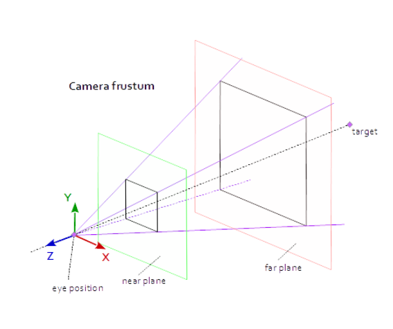
Remember that the perspective camera is modeled as a truncated pyramid called the view frustum.
This frustum consists of a few parts that need to be defined in order to create our projection matrix. Here are those parts:
- Near plane - this is the distance to the
nearclipping plane through the negative z axis (defined in camera space) - Far plane - this is the distance to the
farclipping plane through the negative z axis (defined in camera space) - Field of view (fov_y) - this is the angle between the top and bottom sides of the frustum.
- Aspect ratio - this is the aspect ratio of our window.
The distance between the near and far planes should be as short as possible to minimize the depth buffer accuracy issue or to avoid z-fighting.
💡 Calculating the projection matrix of a perspective camera
Let’s do this calculation assuming our scene uses a perspective camera. Remember that there is a difference between modeling a perspective camera and an orthographic camera.
With gl-matrix our job is very simple. We just need to pass some parameters to the method as follows:
    const aspect = this._context.canvas.width / this._context.canvas.height;
    const projectionMatrix = mat4.create();
    const fov_y = (2 * Math.PI) / 5
    const near = 1
    const far = 100

    mat4.perspective(projectionMatrix, fov_y, aspect, near, far);
If there’s any chance you need to build the array yourself, it won’t be too bad:
Note that there is a -1 at the matrix position [3][2] (assuming the matrix is indexed to 0) because the z component in view space (which is negative) becomes our component w after being multiplied by the projection matrix:
💡 NB. Refer to this illustration and note the difference in z-axis direction in camera space and clip space. Spoiler: the right handed coordinate system becomes left handed.
Let’s keep this perspective model in our back pocket as we continue the story of vertex transformation through two spaces that play an important role during the rendering pipeline - clip space and NDC (normalized coordinates).
But before we go there, we have one more stop… homogeneous coordinates.
Homogeneous coordinates
Ah, homogeneous coordinates scared me a week ago. I quickly realized that they are anything but scary. They’re actually super useful to have in our 3D toolbox.
So, to start our discussion, let’s take the example of a vertex positioned in our triangle from two weeks ago like so:
Why is there four dimensions? The position of this vertex is considered a homogeneous coordinate because there is a fourth component, w. We have been working with them from the start!
We need this fourth dimension for a few reasons. We’ll see how we use them, but also how the GPU uses them (to change from clip space to NDC) in the next part.
Applications
There are several applications that will prove useful to us immediately. Note that this list is not entirely complete. The application of homogeneous coordinates is vast!
The projection transformation
We use homogeneous coordinates to work in projective space.
Let’s take a look at an example in 2D to simplify the concept:
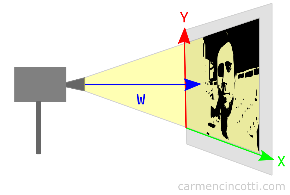
Looking at the illustration, we can see that w has something to do with projection. Let’s imagine that we bring the movie projector closer to the screen.
The image should shrink! In addition, if we move the movie projector away from the screen, the image should get bigger! It can therefore be deduced that the w component affects the scale of the image with respect to the projection.
We will see later how this value is used by our GPU to render the image with an illusion of correct perspective.
💡 Does w = 1 all the time?
I think the first question to ask is: w = 1, what does that mean?
As we just saw, the w value describes the scale of our components relative to the distance of the projection. A value of 1 therefore means that no scaling occurs. Thus, when w = 1, it has no effect on the values of the x, y or z components.
So setting w = 1 is a very reasonable initial value. In the code, when we define our vertices, we set the value to 1, which essentially delegates the responsibility of updating this component to the projection matrix.
So once all the calculations are done, w will probably no longer be equal to 1.
The translation of 3D coordinates
This application is used extensively in the graphics world. In fact, we already saw this a week ago with our 4D lookAt and viewMatrix matrices.
Usually the translation vector is written as a 3D vector, and is considered an affine transformation. Additionally, the rotation and scaling matrices are also 3D (3x3):
Is it possible to represent an entire transformation (translation, rotation, scale) in a single matrix? Yes! By adding the 4th component, w, we harness the power of the 4th dimension:
As soon as we add this fourth dimension, we can then multiply these matrices to build a single matrix, just like last week when we were introduced to the viewMatrix:
💡 To learn more, a good resource that I recommend watching is Keenan Crane’s YouTube channel.
Clip space
Clip space - what is it? I think this illustration can help us see things more clearly:
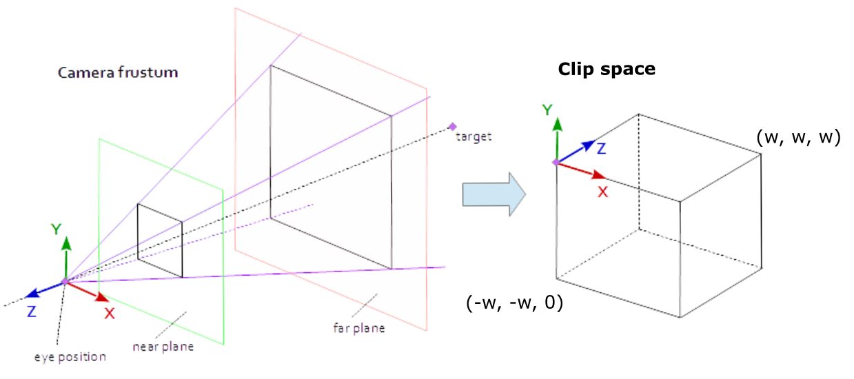
In short, clip space is modeled as a prism, which is called the clip volume. If there are vertices of a primitive that are outside of this space, they will be rejected (clipped) by our GPU. It does this in order to avoid unnecessary calculations since we can’t see those vertices, anyway.
The clip volume dimensions are defined as the following bounding box: where is the extra dimension of the vertex, which makes the vertex a homogeneous coordinate!
In order to avoid being rejected by our GPU, the x, y , and z components in clip space must meet these conditions :
How to enter clip space
Our vertices are positioned in clip space by us.
How so? The calculations involved in transforming our vertex positioned in model space into clip space happen in the vertex shader. In fact, the position we set as output, is the position in clip space.
The equation typically used in a vertex shader is:
out.position = projectionMatrix * viewMatrix * modelMatrix * inputModelSpacePosition
where:
- inputPosition - the 4D vertex position (homogeneous coordinate) in model space.
- modelMatrix - the 4x4 matrix that transforms input vertices from model space to world space.
- viewMatrix - the 4x4 view matrix, which takes as input a point in world space and the result is a point in camera space.
- projectionMatrix - the 4x4 projection matrix, which takes as input a point in camera space and the result is a projected point in clip space.
What’s a little confusing to me is the fact that each vertex can have a different wc value. So we should think of clip space as a rectangular prism and every vertex has its own clip space in which it exists..
💡 What about the triangle that has vertices both inside and outside the clip volume?
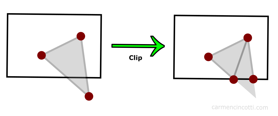
Our GPU is very smart. Using an algorithm (which I won’t go into in depth in this article), vertices outside the clip space are clipped, and the GPU redraws other vertices in their place as illustrated in the figure above.
The result is a cut primitive, but still present in the scene. These new vertices can create the additional triangles if the GPU deems it necessary.
NDC
After clipping the vertices that are outside the clip volume, the positions of the remaining vertices are normalized to a common coordinate system called NDC (Normalized Device Coordinates).
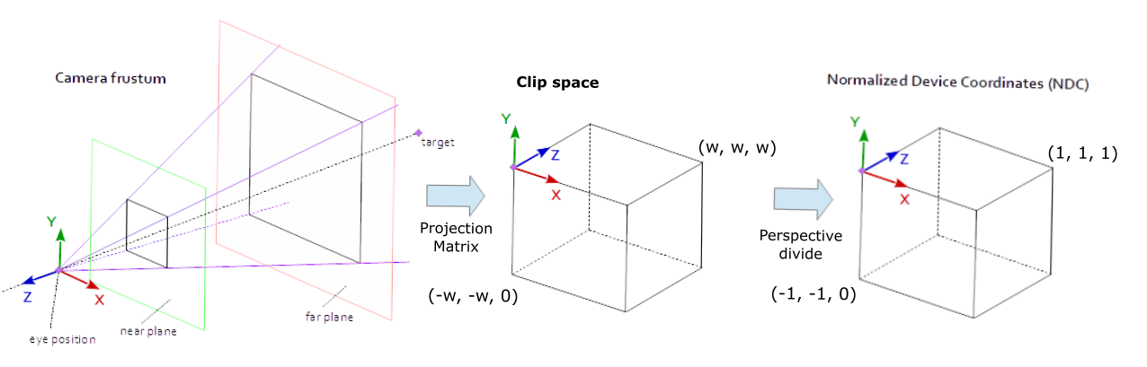
The GPU does the work of getting into this coordinate system by performing an operation called perspective divide where all vertex components are divided by the w component.
Recall that we just clipped all vertices that were outside the w dimension prism. So our components should be between -1 and 1 after normalizing them by dividing the x and y components by the w component. For the z component, the normalized coordinates will be between 0 and 1.
⚠️ Each graphics API is different and you should consult the documentation for the graphics API you are using, but in the case of WebGPU, NDC is between (-1, -1, 0) and ( 1, 1, 1).
Next time
We continue this story by seeing how we get to 2D screen space from NDC!
Resources
- Stack Exchange - Why is clip space always referred to as “homogeneous clip space”?
- Tom Dalling - Explaining Homogeneous Coordinates & Projective Geometry
- Stack Overflow - No, clip space and NDC space are not the same thing.
- Scratchapixel - The Perspective and Orthographic Projection Matrix
- Songho.ca - OpenGL Projection Matrix
- WebGPU - Point Rasterization
- Keenan Crane - Homogeneous Coordinates
Comments for Homogeneous Coordinates, Clip Space, and NDC | WebGPU
Written by Carmen Cincotti, computer graphics enthusiast, language learner, and improv actor currently living in San Francisco, CA. Follow @CarmenCincotti