
This week I continued to learn more about the elements needed to create a 3D scene with WebGPU. I got to the point where I wanted to introduce the ability to move the camera. Indeed, during its implementation, I quickly realized that the theory of a 3D camera is not trivial. The theory is a gateway to the knowledge needed to understand how to create and multiply transformative matrices to stage our 3D objects.
⚠️ This article is a continuation of our discussion from last week. I recommend that you read it again to better understand the context of the content we are about to see!
The Camera
Composition, staging and camera movements are the foundations of a story.
The camera is the gateway to our 3D scene. Without it, our scenes would look dull and flat without the ability to distinguish between foreground and background elements, among a huge list of other things.
3D cameras are not real in the sense that they are created by calling a WebGPU function. To simulate them, we need to model them carefully using matrices to manipulate our 3D vertices. After applying a series of transform matrices to the vertices, we can view our world through the camera lens.
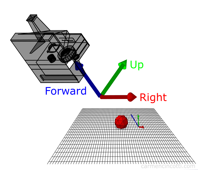
A quick note on some assumptions about our coordinate system…it’s a right-handed coordinate system shown in the image below:

That being said, in world space we assume that:
- the X axis points to the right.
- the Y-axis points up.
- the Z axis points to the screen (us).
But, note the difference in assumption for camera space:
- the X axis points to the right.
- the Y-axis points up.
- the Z axis points towards the scene (away from us) which is the opposite of world space! It is therefore negative with respect to the world coordinate system. We look down the negative z-axis.
So, to get started, let’s first study the eye of a camera and how to create the matrix needed to transform the position of our vertices from world space to camera space.
The eye and the view matrix
The eye is the origin of our camera. We view the scene from this point in 3D space. Our goal is to transform our scene from world space to camera space (view space), which means that we need to transform our coordinate system to be relative to the camera lens with a transformation matrix called the view matrix. A method to construct the view matrix will be through constructing a lookAt matrix, which encodes the position and the target of the camera through translation and rotation matrices.
The lookAt matrix
We can calculate the direction and rotation of our camera and build a matrix to transform our coordinate system from world space to camera space. We need to find our camera vectors to build our rotation matrix.
Foward vector (z axis)
To calculate the directional forwardVector in which our forward axis of our camera is pointing at, we just need to subtract the positional vector of the eye of the camera from the position vector of our target. Suppose the camera points to the point (0, 0, 0).
⚠️ NB. Remember to normalize this resulting vector, because a direction vector is a unit vector.
⚠️ NB2. The direction we just calculated is the opposite of the ‘real’ direction because the z axis of our camera is opposite to that of the world!
Right vector (x axis)
Using a little trick, we can find the rightVector directional vector by calculating the cross product between the forwardVector and an arbitrary upward directed vector. An easy choice is the directional vector (0, 1, 0). The result will be a right-pointing perpendicular vector, which will be our rightVector.
Recall that the cross product can be used to find a vector that’s perpendicular to two vectors in 3D space:
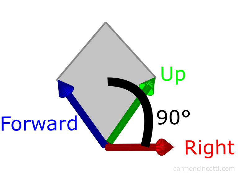
We can leverage this fact to choose a tempUpVector, since it should theoretically be within the plane formed by the real upVector and the forwardVector:
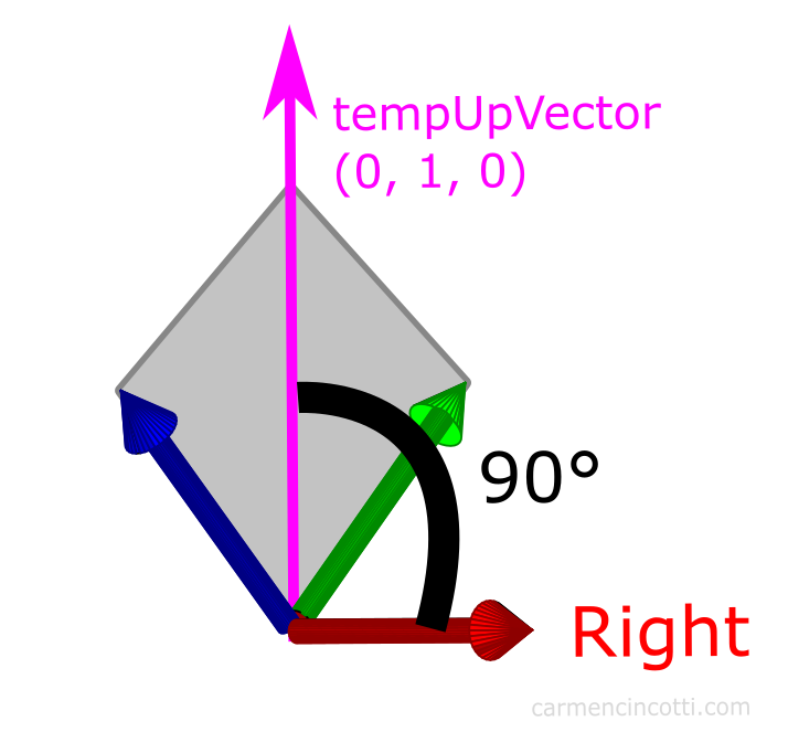
Therefore, our calculation becomes:
Up vector (the y axis)
Finally, we’ll use the trick we just used to calculate the directional upVector of our camera. This time we intersect our rightVector and our forwardVector.
The translation vector
The calculation of the camera translation vector is not well documented in the resources I have read. It is necessary to use the dot product between the calculated vectors and the position of the eye. Be careful because there are a ton of resources out there in the wild that are not correct!
It is calculated this way because of the order of matrix operations. We are rotating first, and then translating. Therefore, it is necessary to calculate the translation of the camera in relation to its new orientation.
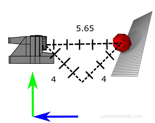
For example, let’s assume our camera starts at (0, 4, 4) in world space. It does not suffice to set the translation vector to (0, 4, 4) like this:
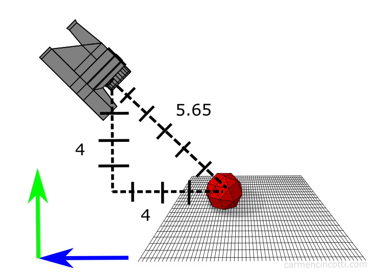
Instead, we need to apply the rotation first, then find the translation vector, which after using our dot product calculations from above, we find that that corresponds to a vector (0, 0, 5.65):
The final lookAt matrix
Our final matrix is as follows:
where R = rightVector, U = upVector and F = forwardVector.
However, in the code, the rotation and the translation are inverted since recall that a ViewMatrix in fact moves the world to make the camera as the origin… be careful here, as this really screwed me up at work one day… the inverse of rotation is the transpose, and finally the inverse of a translation is just its negative self… therefore our viewMatrix is just the inverse of the lookAt matrix:
Implementation code
Using the LookAt matrix as the view matrix, we will transform all coordinates from world space to our camera space, where the camera is looking down the negative z-axis.
After calculating the view matrix, the next matrix to calculate is the projection matrix. The two types of cameras I would like to focus on are perspective cameras and orthographic cameras.
The perspective camera
A perspective camera makes it possible to distinguish the position of the elements in depth. Thanks to the projection, distant objects are smaller than near ones. Our eyes imitate this view. Imagine that we are looking at a forest, the closest trees seem bigger to us than the trees a few kilometers away.

By Wing-Chi Poon - self-made, at Gotier Trace Road, Bastrop State Park, Texas, USA. This area of Texas is known as the Lost Pines Forest., CC BY-SA 2.5, Link
Perspective camera model
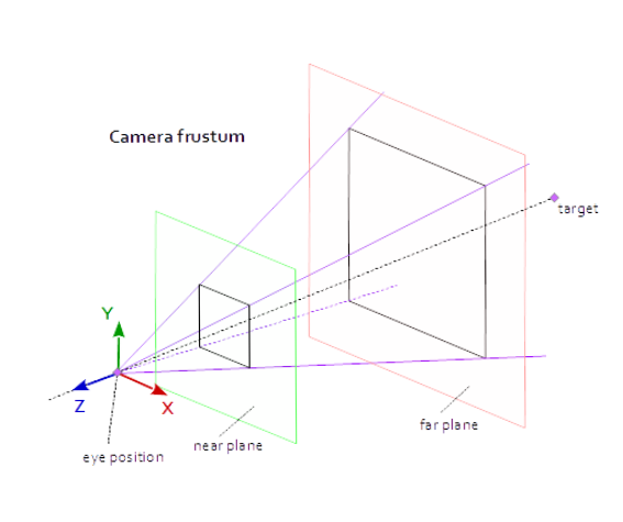
Above is an illustration of the camera geometry which is called the view frustum. The vertices outside the frustum are “clipped” (more on that later). The perspective camera is made up of a few parts that need to be defined in order to create our projection matrix. Here are those parts:
- Near plane - this is the distance to the
nearclipping plane through the negative z axis (defined in camera space) - Far plane - this is the distance to the
farclipping plane through the negative z axis (defined in camera space) - Field of view (fov_y) - this is the angle between the top and bottom sides of the frustum.
- Aspect ratio - this is the aspect ratio of our window.
I recommend that you check out this resource to play around with the different settings to see how view frustum works.
💡 Are the two clipping planes (‘near’ and ‘far’) arbitrarily defined?
The definition of these two planes are responsible for preventing (or causing) something called z-fighting, which is due to floating point comparison issues.
Let us take a contrived example to understand this phenomenon: I place
- Object 1 in camera space @
(0, 0, 50) - Object 2 in camera space @
(0, 0, 55)
…and define my near and far planes of the viewing frustum as 0.1 and 100.
Basically, once we transform coordinates into NDC (we’ll see what this means next week), our Z-buffer coordinates are between 0 and 1 (as defined in WebGPU, be sure to double check if this is the case if you are using a different API).
Therefore, my objects in NDC are now:
- Object 1:
(0, 0, 0.5) - Object 2:
(0, 0, 0.55)
That works fine and no z-fighting will happen since the level of precision should produce no floating point comparison issues.
Now, lets set the near plane to 1e-5 and the far plane to 1e6. Now in NDC, things are didfferent:
- Object 1 will be located at
(0, 0, 0.00004) - Object 2 will be located at
(0, 0, 0.000045)
As you can see, this is a problem as we’re now starting to demand a lot of our computer’s flimsy ability to compare super precise floating points (spoiler: it’s not that great)…
This will certainly cause problems, thus it is important to use reasonable values.
The orthographic camera
With the orthographic camera, all equal objects appear at the same scale. Parallel lines stay parallel, which is different from our perspective camera. This facilitates the evaluation of relative sizes and the alignment of models.

Just like the perspective camera model, we define parameters in order to configure it. We are responsible for defining the near plane and the far plane, as well as the other planes that form the orthogonal projection cube.
Because I’ll be focusing more on perspective cameras in the near future, I won’t be going too into orthographic cameras for now…
Next time
In the following article, we will see the transformations of our coordinates in more detail.
Resources
- Carmen Cincotti - The Magic of the LookAt Matrix
- Carmen Cincotti - Lets Look At Magic LookAt Matrices
- Brown37 - Introduction to Cameras
- Prusa3d - Caméra perspective / orthographique
- Wellesley - Viewports, Aspect Ratio, Depth, Unprojection
- Dustin P Fister - Working with a perspective camera in three.js
- w3 - WebGPU - Coordinate Systems
- Developpez - Apprendre OpenGL moderne
- Brown37 - Perspective Projections
Comments for 3D Cameras | WebGPU
Written by Carmen Cincotti, computer graphics enthusiast, language learner, and improv actor currently living in San Francisco, CA. Follow @CarmenCincotti